Established in 1988China
Currently, the most widely used materials in MBR membrane modules are only polyvinylidene fluoride (PVDF), polyethylene (PE), and polypropylene (PP). Among them, polyvinylidene fluoride (PVDF) is used in the largest volumes both domestically and internationally due to its excellent physical and chemical properties (strength and corrosion resistance).
Membranes used in MBR technology are typically microfiltration (MF) and ultrafiltration (UF) membranes, most with a pore size ranging from 0.1 to 0.4 μm.
Common polymeric materials for microfiltration include: polycarbonate, cellulose esters, polyvinylidene fluoride, polysulfone, polytetrafluoroethylene, polyvinyl chloride, polyetherimide, polypropylene, polyetheretherketone, polyamide, etc.
Common polymeric materials for ultrafiltration include: polysulfone (PS), polyethersulfone (PES), polyamide, polyacrylonitrile (PAN), polyvinylidene fluoride, cellulose esters, polyetheretherketone, polyimide, polyetheramide, etc.
Hollow fiber membrane made of PVDF (Polyvinylidene fluoride) material. PVDF is a fluorinated polymer with a molecular weight of 3-4 million, possessing strong physical strength and chemical stability.
Ceramic membranes are primarily porous membranes made from inorganic materials such as Al2O3, ZrO2, TiO2, and SiO2, with pore sizes ranging from 0.1 to 50 μm.
They exhibit good chemical stability, resistance to acids, alkalis, and organic solvents, high mechanical strength, capability for backwashing, strong resistance to microorganisms, high-temperature resistance, narrow pore size distribution, and high separation efficiency.
Compared to similar organic polymer membranes, ceramic membranes offer many advantages: they are sturdy, stress-resistant, durable, less prone to fouling, and have greater resistance to chemically aggressive liquids and high-temperature cleaning solutions. Their main disadvantages are high cost and a complex manufacturing process.
-----MBR Membrane Modules
1.Hollow Fiber
Leachate treatment equipment manufacturers note that hollow fibers possess strength that resists deformation under high pressure and require no support material. A large number (up to hundreds of thousands) of hollow fiber membranes are housed in a cylindrical pressure vessel. The open ends of the fiber bundle are potted with epoxy resin into a tube sheet. The outer diameter is typically 40–250 μm, and the inner diameter is 25–42 μm. In MBRs, modules are often placed directly into the reactor, requiring no pressure vessel, forming a submerged membrane bioreactor; these are usually outside-in (externally pressurized) membrane modules.
Advantages:High packing density, typically reaching 16,000–30,000 m²/m³; relatively low cost; long service life; can use nylon hollow fiber membranes with stable physicochemical properties and low water permeability; membranes have good pressure resistance and require no support material.
Disadvantages:Sensitive to clogging; fouling and concentration polarization significantly affect membrane separation efficiency; high pressure drop; difficult regeneration and cleaning; high raw material pretreatment cost.
2.Plate and Frame (Flat Sheet)
Plate and frame modules were the earliest form of membrane modules used in MBR technology, resembling standard plate and frame filter presses.
Advantages:Simple manufacturing and assembly, convenient operation, easy maintenance, cleaning, and replacement.
Disadvantages:Relatively complex sealing, high pressure loss, low packing density.
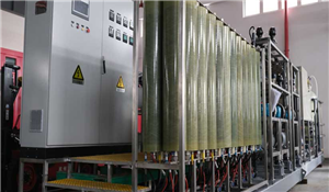
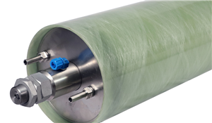
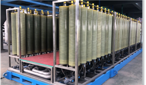
3.Tubular Membranes
Consist of the membrane and its support, can operate in internal or external pressure mode. In practice, internal pressure mode is more common, where feed water flows inside the tube and permeate exits outside the tube. Membrane diameter ranges from 6 to 24 mm. The tubular membrane is placed inside a porous stainless steel, ceramic, or plastic tube; the number of membrane tubes per module is typically 4–18. Current tubular membranes mainly include sintered polyethylene microfiltration membranes, ceramic membranes, porous graphite tubes, etc. They are expensive but fouling-resistant and easy to clean. Especially suitable for high-temperature media.
Advantages:Ability to control turbulent flow of feed liquid, less prone to fouling, easy to clean, low pressure loss.
Disadvantages:Low packing density, usually below 300 m²/m³.
4.Spiral Wound Modules
Main components are porous support material, with membrane on both sides, three sides sealed, the open side sealed and connected to a perforated central product water collection tube. A mesh-type spacer material is placed on the feed side outside the membrane envelope. The membrane envelope-spacer is sequentially layered and tightly wound around the central collection pipe to form a membrane roll, which is installed into a cylindrical pressure container to create a spiral wound membrane module.
Advantages:High membrane packing density; simple membrane support structure; low concentration polarization; easy to adjust flow regime on the membrane surface.
Disadvantages:Potential for leaks at the central tube; membrane can rupture and leak at the bonding point with the support material; difficult membrane installation and replacement.
5.Three Common Types of MBR Membrane Modules
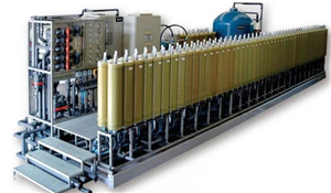
(1) Hollow Fiber Curtain Submerged Modules: Characterized by large membrane area, easy installation, and convenient cleaning.
(2) Hollow Fiber Cylindrical Submerged Modules: Characterized by large membrane area and small footprint.
(3) Flat Sheet Curtain Submerged Modules: Characterized by high membrane flux, easy assembly, and convenient cleaning.
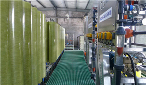
6.MBR System Design-----ZW-MBR Process Composition
(1) Pretreatment – Fine screen, requirement ≤2mm, recommendation ≤1mm, round hole and mesh type / Pretreatment: Screen - GE requirement, Primary Sedimentation Tank, Grit Chamber - decided by designer
(2) Biological Process Part / Decided by GE or designer
(3) Membrane Filtration Part / Membrane technology (or product) decided by GE
(4) Excess Sludge Treatment Part / Sludge dewatering - GE decides whether to add polymer, Digestion treatment - decided by designer, Sludge disposal method - decided by designer
7.MBR Process Route Selection
(1) MBR process flow for domestic sewage;
(2) MBR process flow for industrial wastewater;
(3) MBR process flow focused on ammonia nitrogen removal;
8.Membrane Tank Design
(1) Anoxic Tank Design:
Design principle: Nitrogen volumetric load set below 0.2 kg/(m³·day);
Nitrogen content in water inflowing to anoxic tank: Q2 * C_Ammonia Nitrogen;
Required anoxic tank volume: at least (Q1 * C_Ammonia Nitrogen) / 0.2;
(2) Membrane Tank Design:
Design principle: BOD volumetric load below 2.0 kg-BOD/(m³·day);
Assuming the anoxic tank's BOD removal rate for influent is η (20%–50%), then the BOD concentration entering the membrane bioreactor is C_BOD × (1–20%);
Required membrane bioreactor volume: at least [C_BOD × (1–20%)] / 2.
(3) Membrane Element Selection
① Select appropriate membrane flux;
② Determine the required membrane area;
③ Determine the number of membrane elements based on the membrane area of a single element;
④ MBR membrane operation involves backwashing, etc., so it's necessary to comprehensively consider water utilization rate and element downtime;
9.MBR Permeate (Product Water) System
The permeate system can operate in either continuous or intermittent (on/off) mode. For slightly polluted source water or systems with low MLSS concentration in the MBR tank, permeate can be extracted continuously. For systems with high MLSS, a mode combining suction and pause can be used.
10.MBR Aeration System
Oxygen Demand:The aeration system primarily supplies oxygen for the metabolism and growth of microorganisms in the membrane bioreactor,mainly in three aspects:
(1) Oxygen demand for microbial oxidation and decomposition of organic matter;
(2) Oxygen demand for oxidation and decomposition of microbial cell material itself;
(3) Oxygen demand for oxidation of ammonia nitrogen in the wastewater.
11.Aeration: Energy consumption can be reduced by implementing cyclic aeration.
Previously: 10 sec on, 10 sec off → Now: 10 sec on, 30 sec off. This aeration method requires an even number of membrane trains. Operating two membrane trains simultaneously can reduce energy consumption by 75%; under low flux and low fouling conditions, it can be reduced by 50%; this aeration method reduces shear force on microorganisms, improving floc structure and removal efficiency.
Note:Single membrane train; peak conditions; under high fouling conditions, the 10/30 aeration cannot be used.
12.MBR Backwash System
Based on the principle that organic fouling is effectively removed by alkaline cleaning and scaling (salt deposits) by acid cleaning, the Chemically Enhanced Backwash (CEB) procedure is introduced into MBR membrane operation. Through an operation similar to low-intensity chemical cleaning, MBR membrane fouling is eliminated at the early stage of formation, preventing synergistic deterioration due to untimely membrane recovery.
13.MBR Chemical Dosing System
The frequency and conditions for chemical cleaning are related to the quality of the influent water. Typically, chemical cleaning should be performed every 1–3 months of operation or when the transmembrane pressure (TMP) under the same operating conditions increases by 0.5 bar or more compared to the initial value.


Henan Yuanhede Industrial Technology Co., Ltd.
East Industrial Park, Yuzhou City, Henan Province, China.
(+86)139 3822 7726
info@yhdegroup.com
www.yhdegroup.com